About Kaapo
Kaapo is a generic diagram drawing software developed at University of Helsinki. It's developed by Oops project group as a Software Engineering Project in summer 2005. Kaapo is released under GNU Lesser General Public License.
Because of the extent of project topic, Kaapo aims to be the first evolution version which will be continued by other project groups later. We don't recommend it for end users before all required functionality has been implemented and the usability tests are carried out.
The name Kaapo is an acronym of the Finnish words 'Kaavioiden piirto-ohjelma' meaning 'Diagram Drawing Software'.
Concepts
The concepts and terms used in Kaapo are explained in this section.
Abstract terms
- Attribute
- Property of a diagram, element or connection, such as name. Attributes have a type, such as string.
- Connection
- Relation between two diagram components, which can be either elements or connections. Some connections may be floating: one or both ends are not connected to anything.
- Diagram
- A collection of elements and connections that form a meaningful whole.
- Diagram component
- Element or connection.
- Element
- Basic building block of diagrams. Usually rendered as a solid object with text or other information inside.
- Project
- A collection of one or more related diagrams. Project is the largest unit in Kaapo. Diagrams and diagram components don't exist on their own, but they are part of some project.
Terms related to user interface
- Attribute panel
- A section in the GUI on the right where attributes are shown and edited.
- Direct editing
- Editing element or connection attributes directly on the drawing area.
- Drawing area
- The main area of the GUI where the diagrams is drawn and edited.
- Project tree
- A section on the left where diagrams of the project are shown. Used for navigation. The tree can be collapsed to show elements and connections of each diagram.
Installation
Download the kaapo-0.5.tar.gz file from the project homepage. Unzip the file in the directory of your choice. The program will be unzipped into a new folder called kaapo-0.5. To run the program you need Java Runtime 1.5 (5.0) or later. To start the program use the command 'java -jar Kaapo.jar'. The program is prebuilt so nothing more is needed to run it.
Usage
To add a new diagram, select a diagram type from the drop-down menu and press the Add button. To change the name of the diagram, you can use the edit field over the drawing area or double-click the name on the project tree on the left.
In the upper part of the GUI is a palette that contains the elements and connections of the active diagram. To add an element to a diagram, press down the element icon and click somewhere in the drawing area. You can also add free-form text into any diagram using the Text button in the upper tool panel. Fully floating connections are added in the same manner; see below for adding connections that are connected to elements.
Depending on element type, you can edit the name of the element directly in the drawing area (by double-clicking on the text) or in the attribute panel on the right. If the attribute panel is not visible, use the drag bar on the right border of the drawing area. (There is also a drag bar on the left border for the project tree.) You can also edit the element name by double-clicking on the project tree in the left. Elements can have more properties than just the name; for these, you must use the attribute panel. (Note: in the current version of Kaapo, there are no elements that have more than one attribute.)
Depending on the element type, you can resize the element using the blue spots on the element when the element is selected.
To add a connection between two elements:
- press down a connection button on the connection palette
- click on the start element on the drawing area
- click on the end element on the drawing area
You can reposition the ends of a connection by selecting the connection and dragging on the blue spots. For connections that have more than one segment, such as the Data Flow connection in Data Flow Diagram, you can edit the segments using the blue spots. Connections have attributes just like elements; they are edited in the same manner. Currently, direct editing is not supported for connections.
To delete an element or a connection, select it and click the red X button or press the Delete key. To delete a diagram, right-click on the diagram name in the project tree on the left and select Delete.
To save a diagram, select Save Project As from the File menu. After the first save, you can use the Save Project entry that saves the diagram to the existing file. To open a diagram, select Open Project from the File menu.
When you have several diagrams in a project, you can use the project tree on the left to navigate. As the name implies, the project tree is a hierarchial tree that has nodes that can be collapsed and de-collapsed.
On the drawing area, you can select several elements and/or connections by drawing an area with the mouse or by clicking with the mouse while the Control key is down. The group can be moved together or the members of the group can be deleted at once.
There is an undo/redo mechanism that should work for all editing actions. (There may be minor bugs in some actions in the current version.) To undo an action, press Control-Z or select Undo from the Edit menu. Redo is done with Control-Shift-Z or with the Redo entry in the menu.
Extending Kaapo
Users familiar with the Java programming language can implement new diagram, element and connection types and write new export or import plugins using the Kaapo extension API. Refer to the API documentation for details on the extension API. It is helpful to inspect implementations of the types and plugins that come with Kaapo. You must have the source distribution of Kaapo.
Rebuilding Kaapo
After you add new classes to Kaapo, you must rebuild the
program JAR file. This is done using
Ant.
Run the command ant in the Kaapo root
directory; the Ant build file build.xml is
located there. For further information on building
Kaapo, see INSTALL.txt in the Kaapo root directory.
On the Linux system of the CS Department of University
of Helsinki, rebuilding can be done with the command
/opt/ant/bin/ant.
Serialization
Kaapo uses Java object serialization for internal saving and
loading. Only data structure -related classes are saved;
subclasses of DCGraphics and such are not saved.
Classes in package kaapo.project are saved
and classes in package kaapo.project.graphics are not.
When you define new project components, you must take care
of three things:
- For classes that are saved, define a
private static final long serialVersionUIDfield that is initialized to some value, e.g.1L. - If your class has fields that should not or can not be saved,
you must mark them with the keyword
transient. Example:protected transient DCGraphics dcgraphics. - Classes that are saved must have a constructor with no parameters. The constructor may be protected.
Diagrams
A new diagram type is added by creating a new class
that extends the kaapo.project.Diagram and
implements its abstract methods. Notice that
Diagram inherits some abstract methods from
ProjectComponent.
The diagram class must be in the package
kaapo.types.diagrams and located in
the directory src/kaapo/types/diagrams.
The type manager finds your class automatically.
The method getLegalDiagramElements should return
a list of elements that are legal in the diagram. The list
contains Class objects for subclasses of
Element. The list can be built with statements
like
getClass().forName("kaapo.types.diagramcomponents.SomeElement").
The method getLegalDiagramConnections is similar,
but returns a list of Class objects for subclasses of
Connection.
You can use existing element and connection classes where appropriate. For example, many UML diagram types use the same element and connection types. In some cases, you don't need to write any new diagram component classes.
Elements and connections
To define a new element or connection type, you must implement two classes:
- a data structure class extending
kaapo.project.Elementorkaapo.project.Connection - a graphics class extending
kaapo.project.graphics.DCGraphicsor some subclass of it.
The naming conventions for these classes are
Element for the data structure class and
ElementGraphics for the graphics class.
Both classes must be in the package
kaapo.types.diagramcomponents.
The corresponing directory is
src/kaapo/types/diagramcomponents.
The type manager finds your classes automatically.
You can put the classes in a subpackage of
diagramcomponents if you want to make the
directory structure cleaner and you can figure out
a logical subpackage. Usually you should put the
classes in the root package, especially if your classes
will be used by more than one diagram type.
You also need two icons: small (16*16 pixel) and large
(24*24 pixel). The icons are loaded and returned by the
getSmallIcon and getLargeIcon
methods, which you must override. Note: currently, the
small icon is not used by Kaapo and is not required.
To connect the data structure class and graphics
class, you must override the method
buildDCGraphics correctly. The method
must return an instance of the graphics class
that you created.
Creating the data structure class should be straightforward.
One thing to note is that if you use attributes, you must
add them in the constructor with the addAttribute
method. Accessing non-existing attributes throws an error.
The graphics class can be more complicated if the graphic representation is complex. However, in some cases you can just derive your graphics class from an existing general-purpose class.
For connection types, you can almost always use the ready-made
kaapo.project.graphics.ConnectionGraphics
class that does the work for you. To use it, define a
new class that inherits from ConnectionGraphics
and call the constructor with the correct line style and
arrow heads. If you need a line head that is not already
defined, see below.
For element types, there is a generic class
for solid elements that have one text section inside
them:
kaapo.project.graphics.SolidGraphics.
The class supports the following shapes:
rectangle, round rectangle, ellipse and circle.
Using this class is as simple as calling the constructor.
However, if your element is graphically more complex,
you must derive a new DCGraphics from
scratch. This is the case for UML class elements, for instance.
Attribute panel
An attribute panel is used in the GUI to modify
project component attributes. There is a generic
attribute panel,
kaapo.project.graphics.GenericAttributePanel,
that is suitable for many attribute types. The generic
panel is used by default; you don't need to write any code.
If it is not enough for you, you can create a new attribute panel
by inheriting the class
kaapo.project.graphics.AttributePanel.
The project components that should use your own attribute
panel must override the method buildAttributePanel.
Note: don't override the public method
getAttributePanel.
New line head
If you need a line head graphics that is not implemented
in Kaapo, you must create a new class that inherits from
kaapo.project.graphics.LineHead. The new
class must be added to kaapo.project.graphics
package. See the API doc for details.
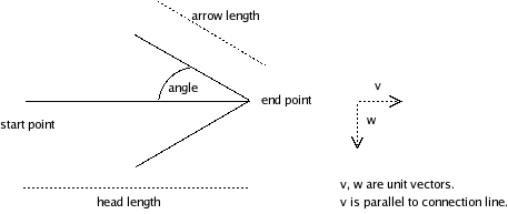
When creating a line head, basic knowledge about
linear algebra is useful. The line head class must be able to draw
the head in any direction.
Below is an image of arrow head geometry that is used by existing line head classes. You are not required to use the same geometry abstractions, but they may be helpful.
Export and import plugins
Most of the export and import functionality is not implemented
in the first version of this program. However, there is an abstract
class kaapo.filemanager.ExportPlugin which the plugin
classes should extend. The same concept should be used for import
plugins. In future, import and export plugins can be copied to a
defined plugin directory by users and the program will load them
automatically at startup.
New plugins can be implemented the same way as new diagrams or diagram components. The plugins hava access to the public methods of the project and it's components.