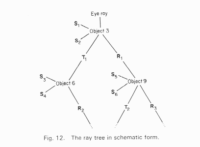
A primary ray is shot through each pixel and tested for intersection against all objects in the scene. If there is an intersection with an object then several other rays are generated. Shadow rays are sent towards all light sources to determine if any objects occlude the intersection spot. In the figure below, the shadow rays are labeled Si and are sent towards the two light sources LA and LB. If the surface is reflective then a reflected ray, Ri, is generated. If the surface is not opaque, then a transmitted ray, Ti, is generated. Each of the secondary rays is tested against all the objects in the scene.

The reflective and/or transmitted rays are continually generated until the ray leaves the scene without hitting any object or a preset recursion level has been reached. This then generates a ray tree, as shown below.

The appropriate local illumination model is applied at each level and the resultant intensity is passed up through the tree, until the primary ray is reached. Thus we can modify the local illumination model by (at each tree node)
I = Ilocal + Kr * R + Kt * T where R is the intensity of light from the reflected ray and T is the intensity of light from the transmitted ray. Kr and Kt are the reflection and transmission coefficients. For a very specular surface, such as plastic, we sometimes do not compute a local intensity, Ilocal, but only use the reflected/transmitted intensity values.